
Scan to BIM LOD in one paragraph
In scan to BIM, the LOD you write into the scope decides what a modeler draws on top of the point cloud and how far your team can trust each element. LOD is set per element, not per model: walls can be LOD 300 while ductwork stays LOD 200. This guide works from the 2025 edition of the BIMForum LOD Specification, the reference most US contracts point to, and applies it to buildings that already exist. If you want the scan and the model done for you, see our page on scan to BIM in Phoenix.
Level of development, defined. LOD is the degree to which a model element's geometry has been thought through, and so the degree to which people using the model may rely on it. It is not the same as level of detail, which only says how much is drawn.
What each scan to BIM LOD means, per the 2025 BIMForum spec
The BIMForum LOD Specification 2025, Part I uses the definitions from AIA Contract Document E201-2022 and adds its own explanation to each. Here they are in plain words, with what each one means when the source is a laser scan rather than a design.
| LOD | Definition, in short | What it means in scan to BIM |
|---|---|---|
| LOD 100 | A symbol or generic representation; information can be derived from other elements | Rarely ordered: the point cloud already tells you more |
| LOD 200 | Generic, recognizable 3D geometry with approximate quantity, size, shape, location and orientation | Placeholders for context: equipment boxes, generic walls in areas you will not touch |
| LOD 300 | Quantity, size, shape, location and orientation can be measured from the model | The working level for renovation design: measured walls, slabs, openings, columns, roof |
| LOD 350 | LOD 300 plus the interfaces with adjacent or dependent elements can be measured | Coordination zones: beam-to-column bearing, duct and pipe penetrations, supports you can see |
| LOD 400 | Detail sufficient for fabrication, assembly and installation | Seldom possible from a scan: bolts, welds and part numbers are not visible |
| LOD 500 | An existing or as-constructed condition from observation, field verification or interpolation; accuracy must be noted | Describes where the geometry came from, not a higher detail level (see below) |
Level of development vs level of detail
Level of detail is how much is drawn. Level of development is how much you can rely on what is drawn. The difference matters more for scans than for design models, because Revit families look finished the moment they are placed. A door family can show hardware and trim while sitting a few inches from the opening in the cloud. The spec is explicit: an element that is highly detailed and geometrically accurate but not located accurately can be no higher than LOD 200.
LOD requirements are minimums, and they stack
Each LOD includes the requirements of the ones below it (LOD 500 is the exception). An element is only at LOD 300 if it meets everything at 100, 200 and 300. That is useful when you check a delivered model: pick an element, measure it against the cloud, and if its location fails, its LOD drops, however much detail it carries.
The 2025 change to openings at LOD 300
Earlier editions asked LOD 300 elements to show openings with any dimension over 6 inches. The 2025 edition dropped that rule. It now asks for all planned openings in structural steel, openings that need formwork in structural concrete, and openings that need extra reinforcement in wood and cold-formed metal framing. For existing buildings, write the opening threshold you need into your scope rather than relying on the old 6-inch habit.
LOD 500 is not a step above LOD 400
Most LOD charts draw LOD 500 as the top rung, labeled "as-built" or "certified". The 2025 spec says otherwise. LOD 500 does not indicate a higher level than LOD 400. It indicates that the element's geometry was determined by observing an existing item rather than designing a future one. The definition also requires that the element's accuracy be stated, and BIMForum recommends the USIBD Level of Accuracy specification for that. The working group even chose not to write element-by-element interpretations for LOD 500, because it concerns field verification rather than modeling.
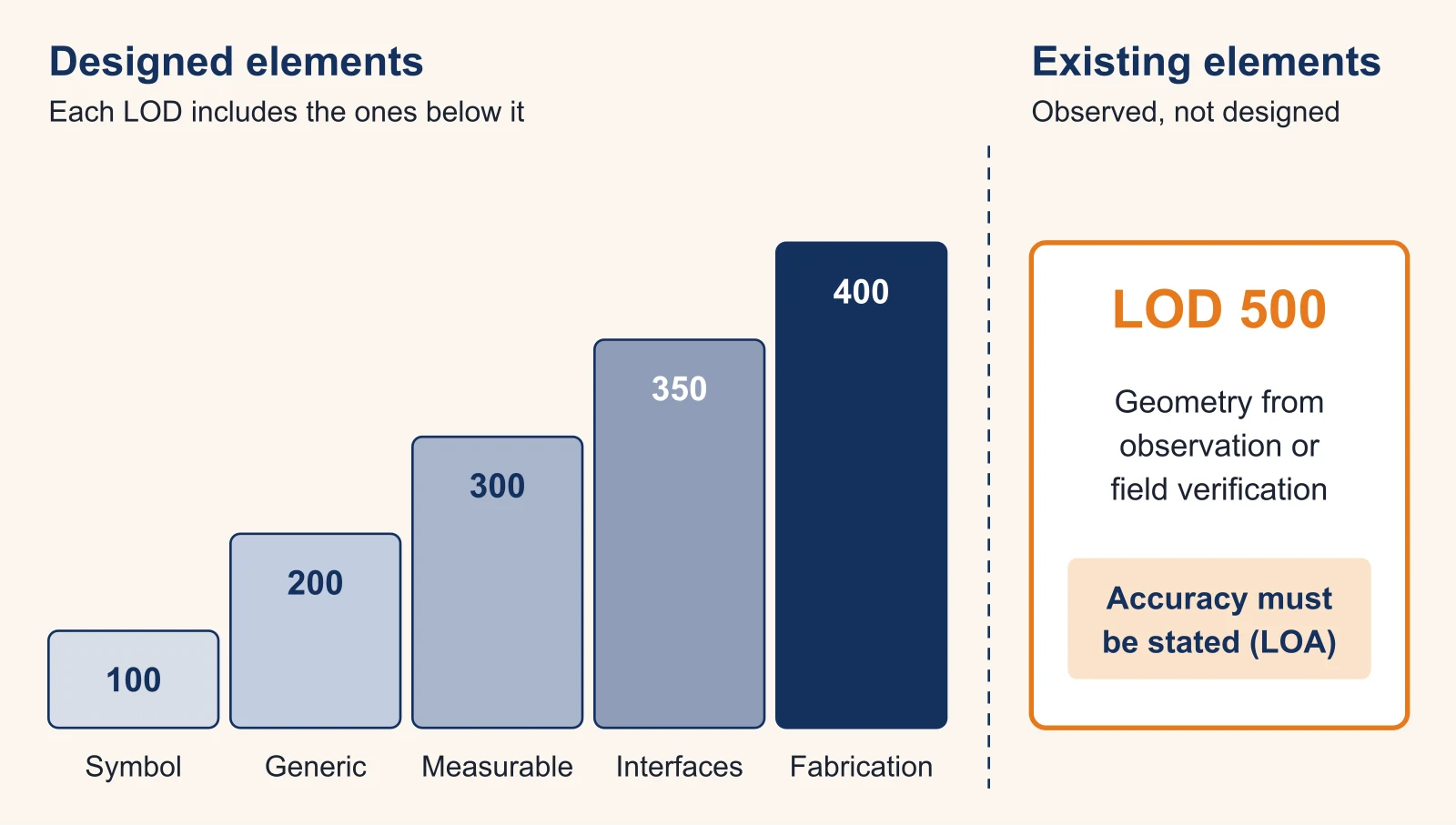
What this means for your scope: "LOD 500 model" is not a meaningful order on its own. Every element in a scan to BIM model is observed, so the useful question is twofold. Which LOD 200, 300 or 350 content do you need for each element, and what accuracy do you need it at?
There is no "LOD 300 model": write an LOD matrix
The spec puts it bluntly: there is no such thing as an "LOD ### model". Any model mixes elements at different levels. A request for "an LOD 300 Revit model" leaves the modeler to guess what you meant for ceilings, rooftop units, conduit and furniture. A short matrix removes the guesswork. This is a starting point for an existing commercial building; change the rows to your project.
| Element | Suggested LOD | Note for the scope |
|---|---|---|
| Exterior walls, interior partitions | 300 | Modeled at measured thickness and location; state whether out-of-plumb walls are modeled plumb |
| Floors, slabs, slab edges | 300 | State whether slab slope or deflection is modeled or noted |
| Doors, windows, storefront | 300 | Sized and placed; hardware not modeled |
| Columns, beams, joists you can see | 300, or 350 where new work connects | Joists often modeled as a pattern from measured samples |
| Roof surface, parapets, roof drains | 300 | Needs a roof-top scan, not only interior setups |
| Rooftop units, major equipment | 200 | Box at measured footprint and height, with clearance zone if needed |
| Main ducts and pipes (visible) | 200 or 300 | Set a minimum size; smaller runs stay in the cloud |
| Ceilings | 300 for heights, 200 for grid | Ceiling height is often what designers need most |
| Concealed elements | Not modeled | Anything the scanner cannot see (next section) |
BIMForum publishes a Part II spreadsheet with the full element list organized by Uniformat; it is the long form of this table. For a single building, the short form above is usually enough to get comparable quotes.
LOD 200 vs 300 vs 350 vs 400 for a scanned building
The question in the secondary searches, "LOD 200 vs 300 vs 400 for scan to BIM", comes down to what you will do with the model. This table compares the four on the decisions a buyer makes.
| LOD 200 | LOD 300 | LOD 350 | LOD 400 | |
|---|---|---|---|---|
| Can you dimension from it? | No, approximate | Yes | Yes, plus connections | Yes, to fabrication detail |
| Typical use on existing buildings | Space planning, context, leasing studies | Renovation design, construction documents, tenant improvements | MEP or structural coordination around existing systems | Prefabricated elements that must fit existing conditions |
| Can the scan support it? | Yes | Yes, for visible surfaces | Only where interfaces are visible | Rarely: needs shop drawings or field inspection |
| Modeling effort | Lowest | Higher | Higher again, local | Highest, selective |
Scan to BIM LOD 200
LOD 200 elements are recognizable but approximate. Use it for everything you will not design against: neighboring tenant spaces, equipment you will keep, site context. It keeps the model light and the cost down.
Scan to BIM LOD 300
LOD 300 is the level most renovation teams mean when they say "existing conditions model". The spec notes that LOD 300 elements are not necessarily clash-free; they are modeled at accurate size so you can judge the space they take. If you plan to run clash detection in Navisworks between new and existing work, LOD 300 is the floor, and LOD 350 is where coordination becomes reliable.
Scan to BIM LOD 350
LOD 350 exists because coordination needs more than measured elements: it needs to know where they meet. BIMForum notes that it usually requires craft knowledge. On a scan, apply it to rooms where it pays, such as mechanical rooms and congested corridors, not to the whole building.
LOD 400 from a scan
The spec describes LOD 400 as the level of shop drawings and notes that most models contain few if any LOD 400 elements. A laser scanner captures surfaces, not part numbers or weld details. If a fabricator needs LOD 400, the scan gives them the measured envelope to fit into; the detail comes from their own shop drawings.
What a laser scanner cannot see caps the LOD
A terrestrial laser scanner records the surfaces in its line of sight. Everything else is inferred, and an inferred element cannot honestly carry an LOD 300 label for location. Before you set the matrix, check what the scan will actually see.
- Inside walls: studs, conduit, plumbing and blocking are not captured. Wall assemblies are modeled from measured thickness; the build-up is assumed or taken from drawings.
- Above hard ceilings: drywall ceilings hide everything above. Lay-in grid ceilings can be scanned above only if tiles are lifted, which takes time and access approval.
- Roofs: an interior scan sees the underside of the deck and the joists; the roof surface, parapets and rooftop units need setups on the roof.
- Behind equipment and stored goods: racking, inventory and furniture block the scanner. Occupied buildings have gaps unless spaces are cleared.
- Underground and in-slab: under-slab plumbing and in-slab conduit are invisible to a laser.
Where an element is hidden, the honest options are to leave it out, model it at LOD 200 from drawings and label it as such, or open it up and scan again. Ask any provider which they will do. Our guide to point cloud file formats explains how to get the registered cloud itself, so your team can check coverage before modeling starts.
LOD is not accuracy: add an LOA line to the scope
LOD says what is modeled and how far it is developed. It does not say how close the model is to the real building. That is a separate requirement, and the BIMForum spec points to the USIBD Level of Accuracy (LOA) Specification, now at version 3.1, for it. The LOA uses five levels, LOA10 to LOA50, from coarsest to tightest, and version 3.1 adds a section on specifying tolerances with standard deviation. In practice, write two lines for each element group: the LOD, and the LOA you need it at. Ask for the measured accuracy of the point cloud as well, since the model cannot be more accurate than the scan under it.
For scale: Sonoran 3D Scanning's typical scan accuracy is ±2 to 6 mm at typical working ranges, depending on scanner, range and conditions. Our deliverables are informational and non-certified. If you need certified measurements, use an Arizona-registered land surveyor.
LOD matrices for two Phoenix building types
Much of the commercial stock around Phoenix and Maricopa County falls into a few repeating types. Two of them show how the matrix changes with the building. Both examples are illustrative, not projects we completed.
Tilt-up concrete warehouse being converted to offices
Tilt-up concrete wall panels, a steel joist and joist girder roof on columns, a metal deck, and rooftop units. The design work is new offices inside the shell and new mechanical on the roof.
| Element | LOD | Why |
|---|---|---|
| Tilt-up panels, openings, dock doors | 300 | New openings will be cut; panel joints and sizes matter |
| Columns and joist girders | 300 | New partitions and ceilings work around them |
| Open-web joists | 300 as a measured pattern | Spacing and depth set the new ceiling height |
| Roof deck, drains, rooftop units | 300 deck, 200 units | New units need structure and clearance; existing ones only a footprint |
| Slab, trenches, pits | 300 | Slab level controls new plumbing routes |
1970s-80s strip retail center, tenant improvement
CMU demising walls, storefront glazing, a bar-joist roof and a lay-in ceiling, with years of past tenant changes that no drawing records. The design work is one or two suites.
| Element | LOD | Why |
|---|---|---|
| Suite walls, storefront, doors | 300 | The new layout is drawn against them |
| Neighboring suites | 200 or excluded | Context only |
| Ceiling height and grid | 300 height, 200 grid | Ceiling height drives the new design; grid is replaced |
| Above-ceiling ducts | 200, or 350 if tiles are lifted | Only modeled as well as the scan sees them |
| Exterior facade | 300 for the suite frontage | Signage and storefront changes need it |
When a tenant improvement needs a City of Phoenix permit, the permit drawings are prepared and submitted by your architect or design professional. A scan to BIM model is the measured base they work from, not a permit document by itself.
How the LOD moves cost and schedule
Higher LOD means more modeling hours, and LOD 350 adds time wherever it applies. The cheapest way to cut a scan to BIM budget is not to drop the whole model to LOD 200, but to limit LOD 300 and 350 to the areas you will change. A second lever is the scan itself: it should be planned for the highest LOD you will ever need, because going back to site costs more than a few extra setups. Raising the LOD later is possible if the cloud covers the elements, but it means revisiting each element.
For what drives the total price, see our guide to 3D laser scanning cost. For a number on your building, our page on scan to BIM in Phoenix lists what we need to quote, or you can send the building and your LOD matrix for a quote.
What to write in a scan to BIM scope
- What the model is for: design, coordination, facility management, or leasing. The purpose decides most of the matrix.
- The LOD matrix: LOD per element group and area, not one number for the building.
- The accuracy: an LOA per element group, plus the measured accuracy of the point cloud.
- Exclusions: concealed elements, minimum pipe and duct size, furniture, and what happens where the scan cannot see.
- Model setup: Revit release, template, levels, worksets, and whether you need an IFC or an AutoCAD DWG export.
- The point cloud: registered, in the format your team can open, delivered with the model so anyone can check one against the other.
Frequently asked questions
What does BIM LOD stand for?
LOD stands for level of development: the degree to which an element's geometry has been thought through, and so how far the project team may rely on it. People also read it as level of detail, but the BIMForum LOD Specification uses level of development. A very detailed element that is placed in the wrong spot is still only LOD 200.
What LOD is best for scan to BIM?
For renovation design and most tenant improvements, LOD 300 for the elements you will design against, and LOD 200 for the rest. Add LOD 350 only where new systems must be coordinated with existing ones, such as a mechanical room or a congested ceiling. LOD 400 is rarely worth asking for from a scan, because a scanner does not see fabrication detail.
What is the difference between LOD 300 and LOD 350?
At LOD 300 an element's quantity, size, shape, location and orientation can be measured from the model. LOD 350 adds its interfaces with adjacent elements, such as where a beam bears on a column or where a duct passes through a wall. LOD 350 is meant for construction-level coordination.
Is LOD 500 higher than LOD 400?
No. The 2025 BIMForum LOD Specification says LOD 500 does not indicate a higher level than LOD 400. It means the element's geometry comes from observing an existing item rather than designing a future one, and its accuracy must be stated, for example with the USIBD Level of Accuracy specification.
Does a point cloud have an LOD?
No. LOD describes modeled elements. A registered point cloud is measurement data: it has an accuracy, not a level of development. The model built from it gets an LOD per element.
What is the difference between CAD to BIM and scan to BIM?
CAD to BIM rebuilds a model from existing 2D drawings, so it inherits whatever errors and missing changes those drawings carry. Scan to BIM models the building from a laser scan of what is actually there. For an older building whose plans no longer match the site, scan to BIM is the safer base.
How much does scan to BIM cost?
It depends on floor area, the LOD per element, the disciplines modeled, access and deadline. Most commercial scanning projects we quote in Phoenix range from $2,500 to $15,000, with a detailed quote before any work starts.