
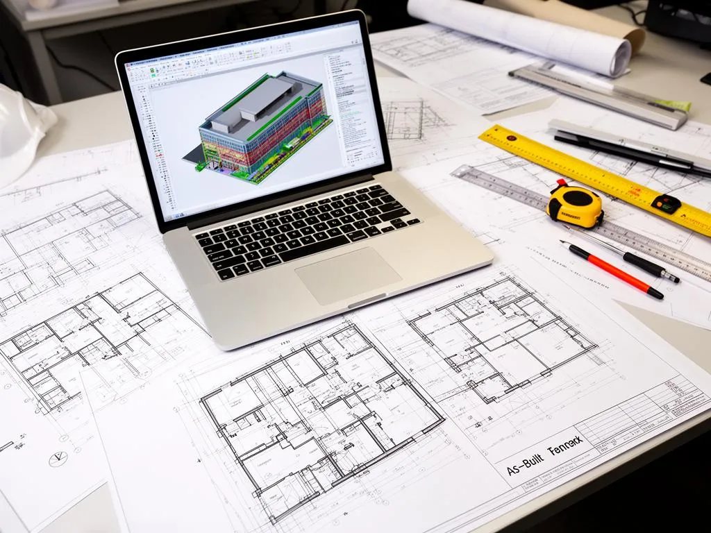
Scan to CAD in Phoenix: what the service is
Scan to CAD is the drafting step that turns a laser scan into CAD. A tripod-mounted 3D laser scanner records millions of measured points of a building. Those points, registered into one point cloud, are accurate but not usable as drawings: you cannot dimension a cloud of dots or hand it to a mechanical engineer as a background. Our drafters cut the cloud at set heights, trace walls, openings and fixed elements as clean lines, and save them as a 2D AutoCAD DWG in your layer and unit standard. In Phoenix and the rest of Maricopa County, that is what CAD teams ask for when they need an existing-conditions background fast and do not want to field-measure an occupied building with a tape.
The service is for the people who will open the file and keep working in it: architects' CAD staff, MEP and structural engineers, tenant-improvement designers, facility managers and property groups who maintain a plan library. It is part of our laser scanning services for commercial and industrial buildings.
Scan to CAD vs as-built drawings vs scan to BIM
The three services start from the same scan. They differ in who receives the result and what it is for. If you are an owner or architect who needs a finished existing-conditions set to design from or to hand to a permit reviewer, you want as-built drawings in Phoenix. If you need a 3D Revit model, you want scan to BIM. If your team has CAD standards and only needs accurate linework in them, scan to CAD is the right scope.
Which service fits your team
| Service | Typical buyer | What you receive | Choose it when |
|---|---|---|---|
| Scan to CAD (this page) | CAD teams, engineers, facility managers | Layered DWG linework built to your layer names, units and title block | You will keep drafting in the file and need it to drop into your project set |
| As-built drawings | Owners, architects, permit applicants | A finished existing-conditions drawing set (plans, elevations, sections) with PDFs | You need a complete, readable set as a design or permit base |
| Scan to BIM | Design-build, BIM coordinators | A 3D Revit model (RVT) at an agreed level of development | You coordinate in 3D, run clash detection or plan in Revit |
| Point cloud only | Teams with in-house modelers | Registered, cleaned point cloud (E57, RCP/RCS, LAS) | You will draft or model it yourself; see point cloud services |
Buildings, not machined parts
Search for "scan to CAD" and you will find handheld scanners and reverse-engineering software that rebuild a machined part as a solid model. That is a different trade. We scan buildings, sites and facilities and deliver architectural and facility drawings. We also do not convert paper blueprints into CAD by tracing scanned images; our CAD comes from measured 3D scan data.
How a point cloud becomes CAD linework
A floor plan is a horizontal cut through the building, seen from above. Point cloud to CAD drafting works the same way. We set a cut plane, isolate the points near it, and trace what the cut passes through: walls, columns, door and window openings. Everything below the cut that matters for a plan (casework, plumbing fixtures, floor level changes) is added from the cloud seen from above. The DWG is placed in the same units and coordinates as the registered point cloud, so you can attach the cloud as a reference in AutoCAD and check any line against it.
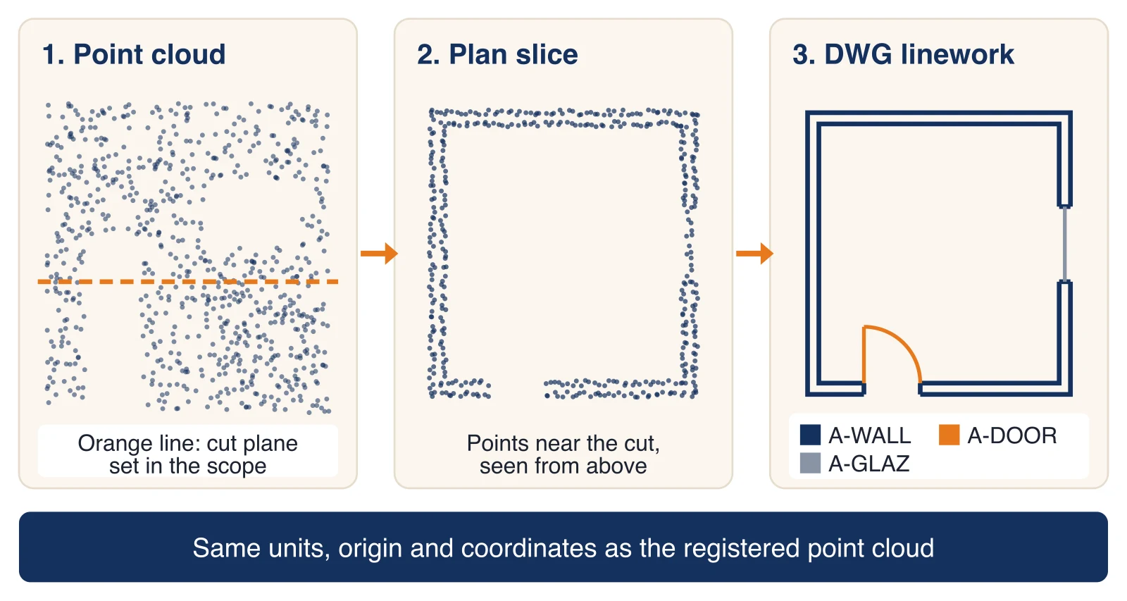
Cut plane and plan slice
The cut height is a scope choice, written into the quote. A common example is 4 ft above the finished floor, which passes through most windows and doors. Buildings with clerestory windows, high sills or mezzanines may need a second cut or a note. For each floor, we also record the finished floor level so the plans stack correctly.
What gets drawn in a scan to CAD floor plan
Disputes on CAD deliverables almost always come from a mismatch between what the client expected and what was drawn. We settle it in the scope sheet, item by item.
Drawn in a typical floor plan scope
- Exterior and interior walls at the cut, with real thickness
- Columns, shafts, stairs, elevators and ramps
- Door and window openings, door swings, frames where visible
- Fixed casework, plumbing fixtures, built-in counters
- Floor level changes and slab edges visible in the scan
- Room names or numbers if you supply them
Drawn only when the scope asks for it
- Ceiling grids, light fixtures, diffusers and access panels (reflected ceiling plan)
- Visible exposed MEP: ducts, pipes, conduit runs, rooftop units
- Electrical panels, outlets and switches visible on walls
- Interior elevations and building sections at locations you choose
Usually left out
Furniture, stored goods, loose equipment, vehicles and people. They are in the point cloud, but drawing them clutters a background that other trades draft on. Anything hidden inside walls or above a closed ceiling is not in the scan, so it cannot be drawn.
Out-of-plumb walls and squaring rules
Real buildings are not square. A laser scan shows walls that lean, bow or meet at 89.6 degrees. You choose how we draw them: as measured (every wall at its true position at the cut height), or rectified (walls snapped to 90 degrees and straight lines when the deviation is under a threshold you set, for example 1 inch). As measured suits renovation and fit checks; rectified suits space planning and leasing plans where clean geometry matters more than the last fraction of an inch.
Scan to CAD deliverables: 2D CAD drawings in DWG
Three of five recent quote requests we were asked to price called for 2D CAD floor plans, from about 20,000 sq ft of commercial space in Phoenix to two adjacent 3-story office buildings totaling about 390,000 sq ft in Scottsdale. Floor plans are the core of most scan to CAD projects; the other drawing types are added as the design needs them.
Floor plans from a laser scan
One plan per level, with walls, openings and fixed elements as listed above, overall and room dimensions if requested, and a north arrow. For property groups and leasing work, plans can be split into suites with room or suite numbers you provide.
Reflected ceiling plans, elevations and sections
Reflected ceiling plans
A reflected ceiling plan (RCP) shows the ceiling as if mirrored onto the floor: grid layout, ceiling heights, lights, diffusers and soffits. It is the drawing tenant-improvement and MEP teams ask for most after the floor plan.
Exterior and interior elevations
Elevations show a facade or a wall face in true dimensions: openings, sill and head heights, storefront mullions, signage areas, equipment on walls. They are drawn from the point cloud viewed straight on, so no photo distortion.
Building sections
A section cuts vertically through the building and shows floor-to-floor heights, structure depth, ceiling space and roof slope. In Phoenix tilt-up warehouses and 1960s to 1980s strip retail, sections are often the only reliable record of clear heights and roof structure.
Site and roof plans
Roof plans show parapets, roof hatches, curbs and rooftop units, which matters in a city where most commercial HVAC sits on the roof. Site plans show building footprints, curbs, parking striping and visible site features. Both are non-certified drawings; they are not boundary or topographic surveys.
CAD file setup: layers, units, title blocks and xrefs
A DWG that measures correctly but ignores your standards costs your team hours of cleanup. These are the specifications CAD managers forget to put in the request, and we ask for them up front.
Layer standards for laser scan to AutoCAD files
U.S. National CAD Standard layer names
If you have no office standard, we use layer names in the format of the AIA CAD Layer Guidelines, which are part of the U.S. National CAD Standard published by the National Institute of Building Sciences (version 7, September 2025). A name starts with a discipline designator (A for architectural) and a four-letter major group, then optional minor groups, separated by dashes. Examples used on scan to CAD plans:
| Layer | Contents |
|---|---|
| A-WALL | Walls at the cut plane |
| A-DOOR | Doors, swings and frames |
| A-GLAZ | Windows, storefront and glazing |
| A-FLOR-CASE | Fixed casework |
| A-FLOR-STRS | Stairs and ramps |
| A-CLNG-GRID | Ceiling grid on reflected ceiling plans |
| A-ANNO-DIMS | Dimensions |
| A-ANNO-TEXT | Room names and notes |
Your office template instead
Send your template DWG or layer list and we draft on it: layer names, colors, lineweights, text styles and dimension styles. A custom standard adds setup time on the first sheet, then none after, so it is worth sending even on small projects.
Units, origin and coordinates
Tell us whether you work in architectural units (feet and inches) or millimeters, and whether the drawing must sit on a project coordinate system or a shared origin from an existing CAD set. By default the DWG shares the origin and orientation of the registered point cloud, so the two overlay. If the cloud is tied to survey control from your surveyor, we keep that control.
Title blocks, sheets and xrefs
We can deliver model-space linework only (best for teams who will build their own sheets), or plotted sheets in your title block. Multi-level buildings are usually split into one DWG per level referenced into sheet files as xrefs, which keeps files small and lets several people work at once. Say which structure you use, and the AutoCAD version your office saves to.
Drafting tolerance for point cloud to CAD drawings
Our laser scans are typically accurate to ±2 to 6 mm at typical working ranges, depending on the scanner, range and conditions. That is about 1/16 to 1/4 inch. Drafting adds its own decisions on top: where a rough wall face is drawn, how a bowed wall is simplified, how dimensions are rounded. The scope sheet states both.
Scan accuracy vs plotted line width
Here is why millimeter scan accuracy is enough for plans. At a plot scale of 1/4 inch = 1 ft (1:48), a thin 0.25 mm pen line covers 0.25 × 48 = 12 mm of the real building. At 1/8 inch = 1 ft (1:96) the same line covers 24 mm. A 6 mm scan error is therefore half a line width or less on a printed plan. Where it does matter is in dimensions and fit checks: a millwork shop or a storefront installer reads the numbers, not the line. For those, ask for dimension rounding that matches the use (for example to the nearest 1/4 inch) and as-measured walls. Our guide on how accurate laser-scanned floor plans are compares scans with tape-measured plans in more detail.
What a CAD drawing from a scan is not
Our scan to CAD drawings are non-certified, informational deliverables. They are not engineering-certified measurements or a licensed land survey, and they carry no seal. For a City of Phoenix permit or Certificate of Occupancy package, your architect or design professional typically uses our DWG as the measured base and seals or submits the plans. If you need a certified survey, use an Arizona-registered land surveyor; we can refer you.
Point cloud to CAD from your own scans
You may already have scan data: from a previous project, a surveyor, or a scanner your team owns. We draft CAD from client-supplied point clouds as well as from our own scans. You skip the site visit cost, and your team keeps a single source of truth.
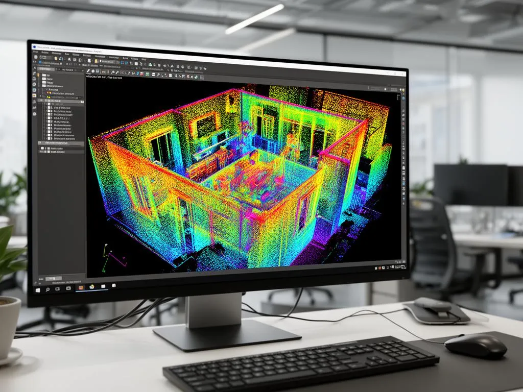
What files to send
- E57: the open, vendor-neutral format; our first choice for exchange.
- RCP/RCS: Autodesk ReCap project and scan files, the formats AutoCAD attaches as point clouds.
- LAS: common for LiDAR and survey data; fine for site and roof work.
- A short note: units, coordinate system or control used, scanner type, date of capture, and which areas were scanned.
When a client-supplied scan needs work first
We review every supplied dataset before quoting the drafting, because problems in the cloud become errors in the CAD.
Checks before drafting
- Registration: are all scan positions joined into one cloud, with a registration report? Unregistered raw scans need processing first, a separate line in the quote.
- Coverage: are all the rooms, ceilings or facades you want drawn actually in the data? Gaps cannot be drafted; they need a return visit or a note on the drawing.
- Noise and density: reflections from glass, moving people or very sparse areas make edges hard to trace.
- Age: a scan from before a renovation shows the building as it was then.
If the review finds gaps in a Phoenix-area building, we can scan just the missing areas and register them to your data, which is usually cheaper than rescanning everything.
How a scan to CAD project runs in Phoenix
- Scope and quote. We confirm the building, drawing types, layer standard, units and deadline, then send a quote. We typically reply to quote requests within one business day.
- Scanning (skipped if you supply scans). Typical commercial buildings take 1 to 3 days on site depending on size. Occupied buildings can be scanned around operations; after-hours or weekend scanning may be available at premium rates.
- Registration and cleanup. All scan positions are registered into one point cloud and noise is removed.
- Drafting. Plans, ceiling plans, elevations and sections are drawn in your CAD setup. Processing and deliverables typically take 3 to 10 business days.
- Delivery and support. You receive the DWG files, PDFs if requested and, on request, the point cloud. We answer questions and handle reasonable revisions and additional extractions.
Scan to CAD turnaround
| Stage | Typical time |
|---|---|
| Reply to your quote request | Within 1 business day |
| On-site scanning, commercial building | 1 to 3 days, depending on size |
| Processing and CAD drafting | 3 to 10 business days |
| Rush delivery | May be available at premium pricing |
Most requests we receive ask for a 1 to 2 week timeline. Tell us the date the drawings are needed when you ask for a quote and we will say whether it is realistic before you commit. Request a scan to CAD quote with your deadline.
Scan to CAD cost in Phoenix
Pricing is project-based, with a detailed quote before any work starts. Most commercial scanning projects in Phoenix range from $2,500 to $15,000. Projects outside the immediate Phoenix area may include travel time charges.
What moves the price
| Driver | Effect on price |
|---|---|
| Square footage and number of levels | More scan positions and more sheets to draft |
| Drawing types | Floor plans only cost least; each added RCP, elevation or section adds drafting time |
| Level of detail | Exposed MEP, wall devices and casework take far longer than walls and openings |
| Building complexity | Many small rooms, curved walls or dense equipment need more scans and more tracing |
| Your CAD standard | A custom template adds setup time once; plotted sheets in your title block add sheet work |
| Access and occupancy | Occupied spaces, lifts, roof access or after-hours work add field time |
| Who scans | Drafting from your own registered scans removes the field cost |
| Deadline | Rush delivery may carry premium pricing |
Worked example: sheets for a 20,000 sq ft floor
Illustrative. Say a one-story Phoenix office building is about 200 ft by 100 ft, so 20,000 sq ft. At 1/8 inch = 1 ft, 200 ft prints at 200 × 1/8 = 25 inches and 100 ft at 12.5 inches, so the whole floor fits on one 36 × 24 inch (ARCH D) sheet with room for the title block. At 1/4 inch = 1 ft, the same floor prints at 50 × 25 inches and no longer fits: it needs two sheets with a match line, or a larger sheet. Deciding the plot scale before drafting tells us how many sheets to set up, which is part of the price, and tells you how readable room labels and dimensions will be. For CAD teams who only want model-space linework, the question disappears.
What to send for a scan to CAD quote
To quote scan to CAD in Phoenix, we need: the address, the square footage and number of levels, whether the building is occupied, the drawing types (floor plans, reflected ceiling plans, elevations, sections, roof or site plan), the CAD format and version and any layer standard or title block, your units, whether you already have scans (and their format), and your deadline.
Photos or an old floor plan help us judge complexity, even if the plan is out of date. We work across the Phoenix metro and Maricopa County, including Scottsdale, Tempe, Mesa, Chandler, Glendale and Gilbert; Prescott, Flagstaff and Tucson are considered case by case. Send your project details for a scan to CAD quote, or call (520) 800-5310.
Frequently asked questions
How much does scan to CAD cost in Phoenix?
Every project is quoted after we see the scope. Most commercial scanning projects in Phoenix fall between $2,500 and $15,000, driven by square footage, the drawing types you need (floor plans only, or also ceiling plans, elevations and sections), the level of detail, access and the deadline. Drafting from scans you already have removes the field cost, so you pay for the CAD work only.
Can you make CAD drawings from a point cloud we already have?
Yes. Send a registered point cloud in E57, RCP/RCS or LAS with its units and any control or coordinate system noted. We check it before quoting: missing rooms, unregistered scans or heavy noise are flagged first, because they change the price and the result.
Do you deliver DWG or DXF, and which AutoCAD version?
The standard deliverable is DWG for AutoCAD, plus a PDF plot set if you want one. If your office runs an older AutoCAD release or another CAD program, tell us the version or ask for DXF in the quote request so we save to a format you can open.
Is scan to CAD the same as as-built drawings?
They use the same scan but serve different buyers. Scan to CAD is the conversion service for CAD teams who will keep drafting in the file. As-built drawings are the finished existing-conditions set an owner or architect uses as a design or permit base.
Can our CAD floor plans be submitted for a City of Phoenix permit?
Our drawings are a measured, non-certified base. Plans in a permit or Certificate of Occupancy package are typically sealed or submitted by your architect or design professional, who works from our DWG. If you need a certified survey, use an Arizona-registered land surveyor; we can refer you.
Can you deliver a Revit model and CAD from the same scan?
Yes. One registered point cloud can feed both a 2D DWG set and a Revit model, so the field work is done once. The Revit side is covered on our scan to BIM in Phoenix page.
Do you reverse engineer machined parts into CAD?
No. Many scan to CAD results online are about scanning mechanical parts into solid models with reverse-engineering software. We document buildings, sites and facilities, and our CAD output is architectural and facility linework.